What this is
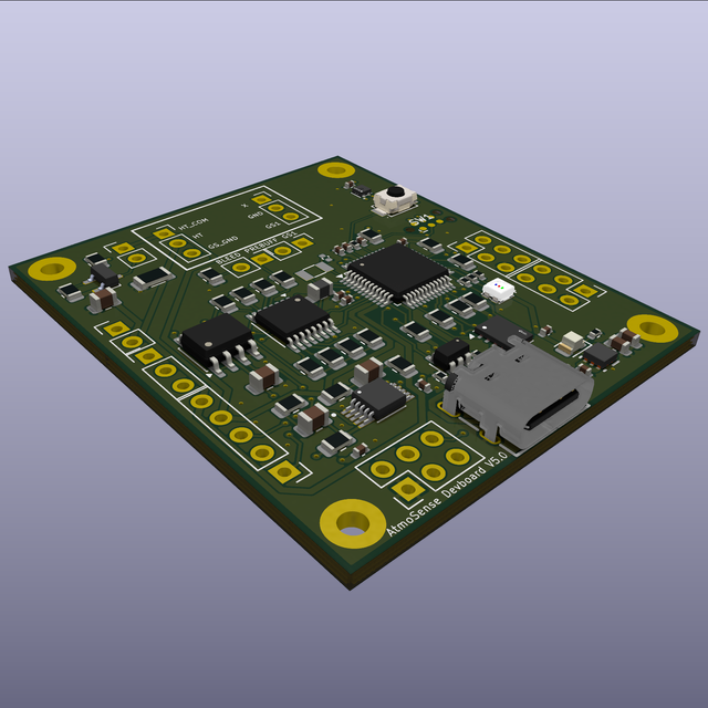
AtmoSense is a startup in San Diego building an ozone sensor. I spent the summer as their hardware intern redesigning the development board that carries the sensing circuit: pulling the ATSAMD21G18A-A off an Adafruit ItsyBitsy M0 module and onto the board itself, bare, while leaving the analog sensing circuit untouched.
The result is V5.0: 41.91 × 48.26 mm, 4-layer, 83 footprints, zero unconnected pads, fabricated and machine-assembled at JLCPCB. Five boards came back, about $30 each, all five powered up.

The measurement problem
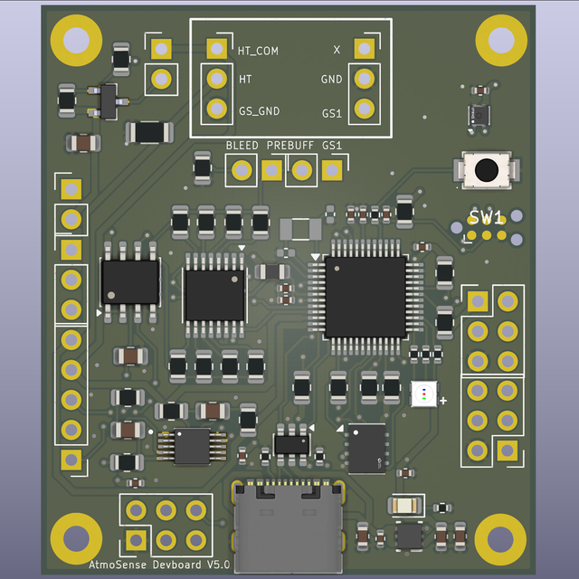
The sensor is a chemiresistor whose resistance swings from a few kΩ to around 800 kΩ with ozone concentration — too wide for one fixed divider. The board’s DAC biases the sensor, an 8:1 analog mux picks from a bank of reference resistors, and a 16-bit ADC reads the result, auto-ranging through the eight channels for resolution:
$$R_{gas} = \frac{R_{ref}}{\dfrac{V_{out}}{V_{bias}} - 1}$$A DMG3415 PMOS switches the heater at 732 Hz PWM, with a 1 Ω shunt so the MCU can back out heater resistance and temperature. An SHT4x covers humidity/temp; a W25Q32 SPI flash logs onboard, with a microSD header for the enclosure.
Power rails and a regulator mistake
VDDCORE is the output of the SAMD21’s internal 1.2 V regulator — tying it to 3.3 V destroys the chip. One cap to ground, nothing else. Everything on the board is 3.3 V native: no USB series resistors, no level shifters.
The real mistake was sizing the LDO against the heater’s average current instead of its peak. Measured peak is 550–580 mA per pulse, because the heater is coldest right when a pulse starts — a 250 mA part would have browned out every cycle. I moved to a 1 A TLV75733 in a 2×2 mm WSON-6, which forced the thermal math:
$$T_J = T_A + P \cdot \theta_{JA}$$At 0.3 A average, \(T_J \approx 58\,°C\) — comfortable under the 125 °C limit. At worst case (100% heater duty, 85 °C ambient), it comes out around 137 °C, over the limit. That’s the number that explained the firmware’s 50% heater duty cap: not an efficiency choice, thermal protection for the regulator.
Layout and SPICE
Placement got redone twice as the board outline changed, and went from miserable to tractable once I started placing functional blocks before individual parts. The real bug: the 576 mA heater pulse was returning through 16.6 mm of surface copper past the analog cluster before finding a ground via. One via on the shunt’s ground pad fixed it.
Two questions got SPICE testbenches instead of guesses. Does the heater pulse sag the 3.3 V rail? About 77 mV droop, fully recovered before the next pulse — fine. Does that droop reach the measurement? The bias path rejects 33 dB of it at 732 Hz, and the ADC’s internal reference doesn’t care about rail ripple at all.
The reference ladder
Originally 1 kΩ–330 kΩ, which left almost no resolution against an 800 kΩ sensor. Revalued to a geometric sweep, ~2.15× per rung:
| Channel | Value | Channel | Value |
|---|---|---|---|
| S1 | 4.7 kΩ | S5 | 100 kΩ |
| S2 | 10 kΩ | S6 | 220 kΩ |
| S3 | 22 kΩ | S7 | 470 kΩ |
| S4 | 47 kΩ | S8 | 1 MΩ |
Every value change has to land in three places — schematic, BOM, firmware constants — and I caught a stale firmware table that still had the old values before it shipped.
Designing for machine assembly
JLCPCB’s real gate isn’t warehouse stock or the “Basic” library flag — it’s “Idle Parts Stock,” a number only visible in their web UI, not the API. Zero idle stock forces a full-reel pre-order even with a Basic part and 700,000 pieces warehoused. It’s also package-specific: 10k/4.7k pull-ups had zero idle stock in 0402/0603 but plenty in 0805, so I moved them. A chunk of the last week was nudging values and packages until everything was Basic and actually orderable.
That $150-for-five figure was the prototype cost. I later built a fuller model separating fab/parts/assembly from shipping and a 35% duty assumption, swept across order quantity:
Full numbers
| Order qty | Ex-works $/board | Landed $/board |
|---|---|---|
| 5 | $25.03 | $42.5 |
| 10 | $17.67 | $27.09 |
| 15 | $17.4 | $25.8 |
| 20 | $15.85 | $23.19 |
| 50 | $12.48 | $17.75 |
| 100 | $11.85 | $17.33 |
| 500 | $9.6 | $13.31 |
| 1,000 | $9.32 | $12.93 |
At 5 boards, shipping and duty add 70% on top of ex-works cost; at 1000 boards, that’s down to 39% — the prototype run pays the steepest tax on both fronts.
Pre-fab review
Full schematic/PCB/EMC/thermal review before release, plus KiCad’s own ERC/DRC. Electrically clean; the real problems were manufacturing ones: 7 vias sitting inside pads (fatal in reflow — paste wicks down an unplugged barrel), and zero fiducials. Both fixed. Everything the review flagged that KiCad’s own DRC didn’t confirm — a claimed ground-plane island, a “missing” LED resistor that was plainly in series — got dropped from the final report. Files win over any tool’s opinion of the files.
Lessons
- Size power against peak current and worst-case ambient, not the bench.
- Do the thermal math early — it changes part choices.
- Manufacturing constraints (package, fiducials, via placement) belong in schematic phase, not after routing.
- When a value changes, grep for it everywhere: schematic, BOM, firmware, docs.
Bring-up
Bootloader went on over SWD from a second dev board acting as a programmer. One trap: SWD can appear to work on a completely unpowered target, because the programmer’s 3.3 V leaks in through the ESD clamp diodes — a Found Target and a passing verify at a sagging voltage that fails later under real load. Power the target from its own USB-C, always.
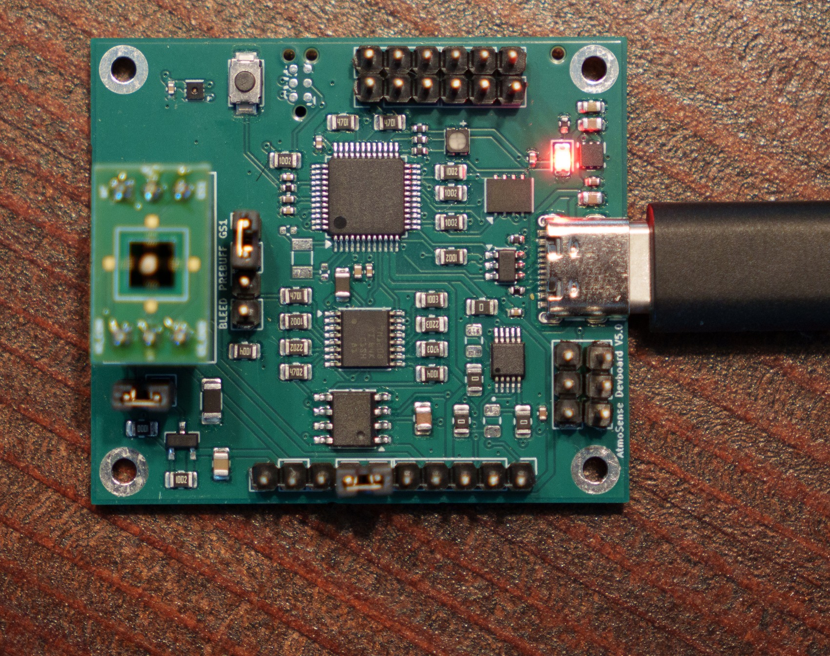
Porting firmware surfaced two silent bugs, same root cause: the stock Arduino board definition I compile against was written for a different Adafruit product on the same chip, so its pin capabilities are wrong for mine. The heater PWM pin is a real timer output in silicon, but the definition marks it as non-PWM — analogWrite() silently falls back to on/off, no error, and the heater just looks broken. Fixed by driving the timer registers directly. The SPI flash chip failed the same way: the definition’s data-in pin is wired to microSD chip-select on this board. Fixed by giving the flash chip its own SPIClass instance on the correct pin.
What real ozone found
Real exposure found the edges of the ladder redesign: baseline ran 1.2 kΩ–45 kΩ across four sensors, and one sensor hit 16 MΩ under ozone — past the top rung. The auto-ranging logic also couldn’t keep up with a fast transient, sitting stuck on the 4.7 kΩ rung through an entire excursion. Eight firmware fixes closed the gap; the one that matters most is a per-row data-quality flag, since \(R_{gas}\)’s denominator collapses near full-scale (58 mV signal against ±4.5 mV op-amp offset at the 16 MΩ peak). Trust below ~200 kΩ, treat above ~2 MΩ as “detected something,” not a precise number.
Separately, the SHT4x reads its own self-heating (+14.7 °C at steady state), not the room. A single exponential didn’t fit; two thermal time constants (90 s / 900 s) do, reaching ±0.2 °C — the sensor’s own spec — within 2 minutes instead of 15.
Validation
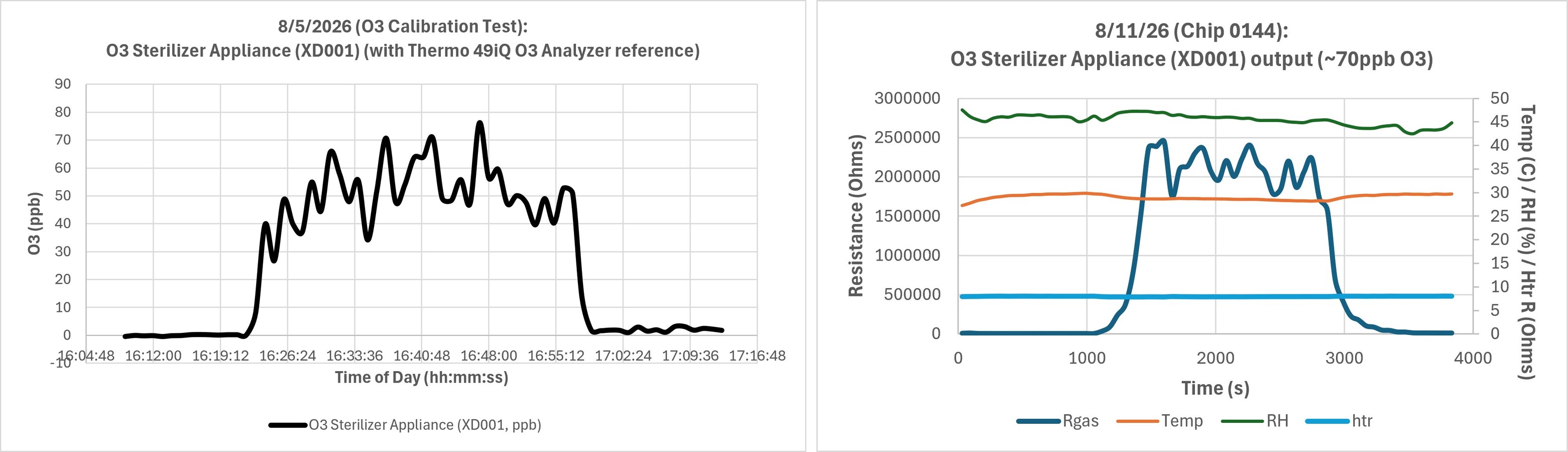
Two real comparisons. First: a Thermo 49iQ lab analyzer characterized an ozone appliance’s actual output (40–75 ppb, noisy plateau, hard cutoff). The board, run against the same appliance six days later, drew the identical shape — 9.1 kΩ to 2.37 MΩ, a 262× swing, 90% rise in 407 s, 90% recovery in 177 s.
Second: a controlled ~10 ppb step from a Teledyne T753U calibrator, on the reworked heater cycle. Earlier runs on the old cycle climbed, peaked, and decayed while true concentration held flat — measuring a re-adsorption rate, not accumulated load. This run holds:
Full numbers
| t (min) | Rgas (Ω) | R / R0 |
|---|---|---|
| 0 | 43732 | 0.97× |
| 10.05 | 45104 | 1.01× |
| 20.11 | 45731 | 1.02× |
| 21.12 | 45025 | 1× |
| 22.12 | 71835 | 1.6× |
| 23.13 | 98492 | 2.2× |
| 24.13 | 152921 | 3.41× |
| 25.14 | 198204 | 4.42× |
| 26.15 | 316006 | 7.04× |
| 27.15 | 373747 | 8.33× |
| 28.16 | 569270 | 12.69× |
| 29.17 | 641594 | 14.3× |
| 32.19 | 629058 | 14.02× |
| 35.2 | 662292 | 14.76× |
| 39.22 | 687135 | 15.32× |
| 43.25 | 683570 | 15.24× |
| 47.27 | 674054 | 15.03× |
| 50.28 | 637182 | 14.21× |
| 53.3 | 379091 | 8.45× |
| 56.32 | 220830 | 4.92× |
| 59.34 | 113192 | 2.52× |
| 62.36 | 70271 | 1.57× |
| 65.37 | 63480 | 1.42× |
| 68.39 | 40642 | 0.91× |
| 71.41 | 39870 | 0.89× |
| 75.43 | 36780 | 0.82× |
| 80.46 | 39649 | 0.88× |
Baseline near 1.0×, peak ~15×, back to baseline — held through the exposure instead of sagging mid-plateau. None of this compares in raw ohms across boards (baselines span 40× board to board), so every number here is a ratio against that board’s own baseline.
Where it landed
Bare chip to fabricated, assembled, flashed, and validated against a real ozone source, on both a lab reference analyzer and a calibrated gas step — that’s the whole arc, design through data. One caveat worth keeping attached to the numbers above: the temperature-calibration constants are bare-board, open-bench figures, so they’re specific to the conditions they were measured under, not a promise that holds in any enclosure.